
Portable Pole
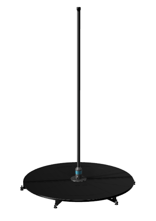
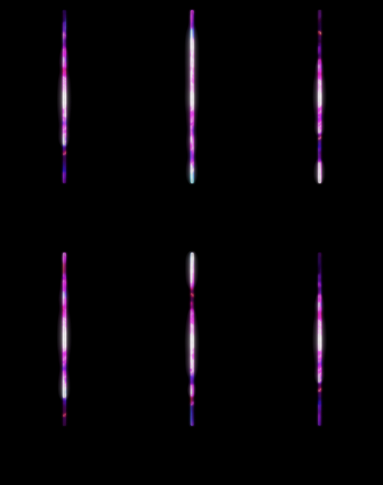
Mounted in an X-Stage Lite by X-Pole, with no top support, so it packs down and travels. Every section of this page is listed under On this page.
Setting one up for the first time? Start at Pole Setup, which is the running order, and follow its links back into the detail.
Specs
The PoleFX portable LED pole is designed to mount in the X-Stage Lite by X-Pole.
| Feature | Description |
|---|---|
| Diameter | 46mm over the polycarbonate, which is the part you dance on |
| Base spigot | 1.5 in steel, the section that enters the stage bearing |
| Power | 5VDC, 60W |
| Data connection | Ethernet |
| Mounting | X-Stage Lite by X-Pole |
A pole has two diameters, and they are not interchangeable. A steel tube runs up the middle of the pole and carries the load. The polycarbonate that lights up goes over it and starts above the base, so the pole measures 46 mm along its lit length and 1.5 in at the spigot that drops into the stage. Quote the 1.5 in figure when the question is about the bearing, and 46 mm when it is about the pole itself.
A portable system is three kits that meet at the stage. Two of them travel in their own cases and one of them can stay with the Player.
- What is in it
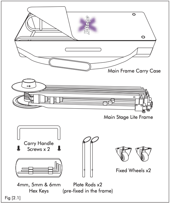
- The main stage frame, six floor plates, X-Pole's own poles and bearing unit, and the 4mm, 5mm and 6mm hex keys.
- How it travels
- Four cases: one for the frame, one for the poles, and two holding three floor plates each.
- Where it comes from
- X-Pole. PoleFX modifies it, or supplies one already modified.
- Carries power?
- No. The stage holds the pole up. Nothing electrical runs through it.
- Watch for
- The hex keys live in the frame case. Without the 5mm key you cannot set static or spin mode.
- What is in it
- The LED pole in one or two sections, its power and data lead, the cable cover, the bearing size adapter, and the replacement screws.
- How it travels
- One 95 in length, or two 53 in lengths. See Sizing.
- Where it comes from
- PoleFX. The adapter and the screws are the parts that make an X-Stage take this pole.
- Carries power?
- Yes. The lead leaves the bottom of the pole and comes out under the stage.
- Watch for
- The adapter and the screws are small and they are the parts you cannot improvise on site.
- What is in it
- The PoleFX Player, the pole's own 5V 12A supply, the Player's own supply, and a Cat5/6 network cable.
- How it travels
- Loose. It does not have to be near the stage, only within cable reach of it.
- Where it comes from
- PoleFX. The same Player drives a permanent or aerial pole.
- Carries power?
- Yes, but not to each other. The pole and the Player each take their own supply.
- Watch for
- The Player has one Ethernet socket. More than one pole reaches it through a switch.
What is in the stage cases comes from X-Pole's X-Stage Lite manual, figures 2.1 and 2.3. The power and data figures are the ones in Input Connections below.
Sizing

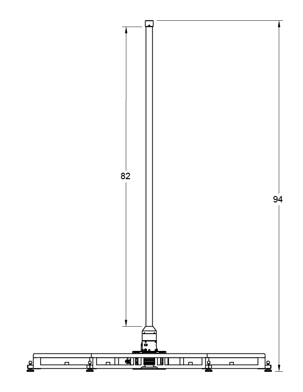


One piece or two
The drawings above are dimensioned in inches. The choice is a transport choice: the two-piece pole is taller once it is up, and it fits in a car.
- Pole length
- 95 in overall, base fitting included.
- Assembled height
- 94 in from the floor, of which 82 in is above the base fitting.
- Sections
- One.
- Where it joins
- Nowhere. There is no coupling.
- Packs as
- A single 95 in length. It will not go in most cars.
- Extra setup
- None. Lift it in and seat it.
- Pole length
- Two sections, 53 in each.
- Assembled height
- 103 in from the floor, of which 89 in is above the base fitting.
- Sections
- Two, upper and lower.
- Where it joins
- About halfway up, where the two sections meet. Two set screws hold the coupling.
- Packs as
- Two 53 in lengths.
- Extra setup
- Two steps. Plug the internal cable together, then align and tighten the coupling. See Pole Coupling.
Every number above is read off the two drawings on this page. If your pole was drawn to a different length, the drawing that came with it wins.
Floor space
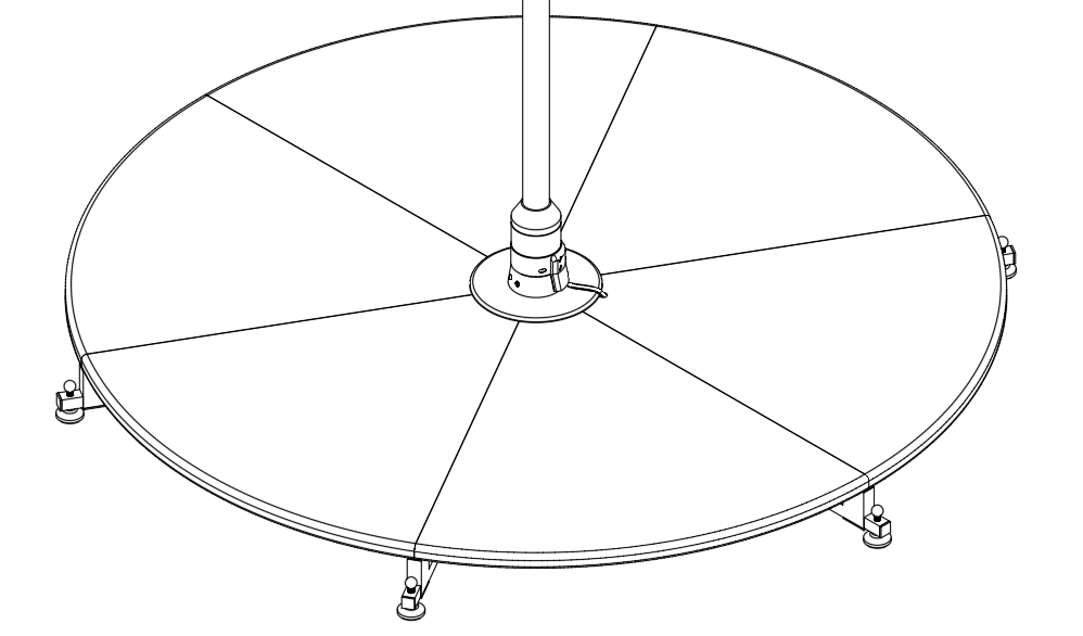 1
2
3
4
5
1
2
3
4
5
- The pole Dead center. Everything else is arranged around it.
- Platform edge The side elevation above measures 64 in across the feet. X-Pole draws the stage as an 800mm radius, so about 1.6m, which is the same number.
- Plate seam Six wedge-shaped floor plates meet at the center. One of the six is the notched plate.
- Adjuster foot Six of them, one per sub-frame. They level the stage and take the movement out of it.
- Cable exit The pole's lead leaves the base, crosses the center plate, and drops through the notch in one plate. Decide which way it runs before you fit the plates.
X-Stage Installation
Familiarize yourself with the stage's normal operation.
Manual and Video
X-Stage Lite Manual
X-Stage Installation Video
Overview
Building on that foundation, we make a few modifications to the X-Stage to support the LED pole.
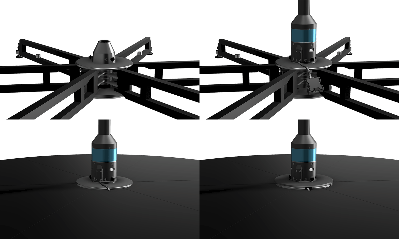
- A power and data cable connected to the bottom of the pole is routed through a notch created in one of the stage plates.
- Connections are made under the stage to a DC power supply and a PoleFX Player via ethernet.
- A cover is then positioned around the pole to protect the cable.
Stage assembly, one frame at a time
The animation above runs once and is easy to miss. Here is the same job as six still steps, with what each one should leave you looking at. These six are X-Pole's own instructions for the stage itself: nothing on this list is specific to PoleFX.
-
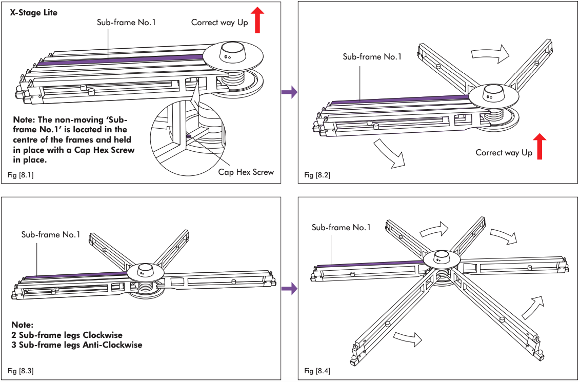
Fan the six sub-frames out
Stand the folded frame in the middle of the floor, correct way up. Find Sub-frame No.1, the one screwed to the plates top and bottom so that it cannot move, and swing the other five out from it. Two go one way and three go the other.
You should see A six-legged star, with the bearing carrier facing up in the middle.
Careful Lift each sub-frame as it swings so it does not drag on the floor.
-
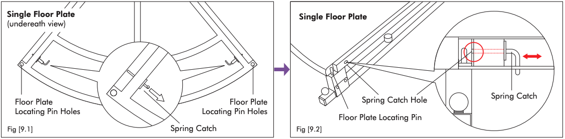
Test one plate's spring catches
Lay a floor plate face down. There are two spring catches, one at each corner of the long curved edge. Turn the pin arm through 90 degrees and let it go.
You should see A pin stand out of the edge of the plate and stay out until you re-secure it. That is the safety catch working.
-
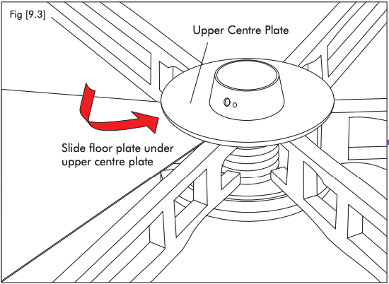
Slide the first plate under the center
Take the plate's narrow end toward the middle of the stage, with its left edge over Sub-frame No.1. The narrow end slides underneath the plate in the middle of the stage, the one X-Pole calls the Upper Centre Plate.
You should see The narrow end disappear under the center plate, and the plate sitting square between two sub-frames.
-
Drop the outer end onto the pin
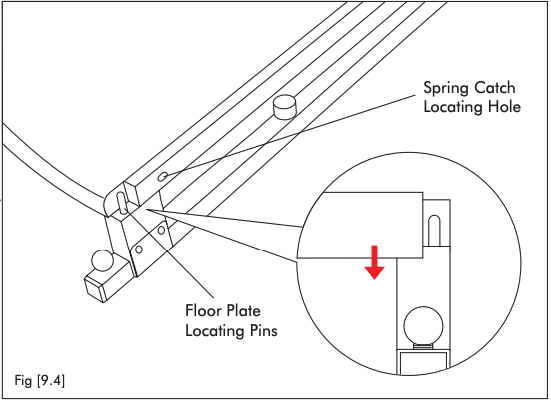
Hold one spring catch back with a finger, lower the outer end of the plate onto the locating pin on the sub-frame, then release the catch. Do the same at the other corner.
You should see The pin come up through the hole in the plate, and the catch snap into the sub-frame.
Careful If the pin will not enter, press the sub-frame tight against the plate edge and keep it parallel. On a new stage you may have to stand on the plate corner.
-
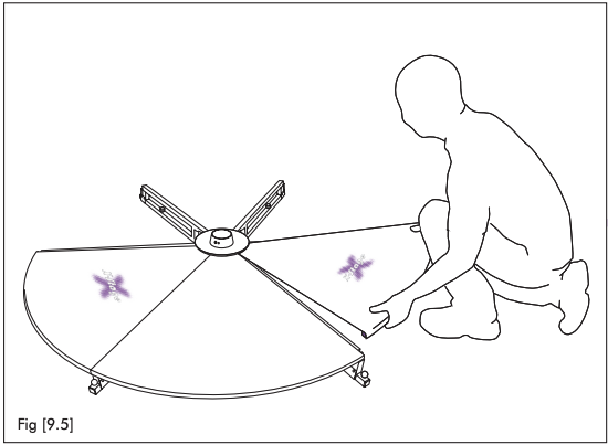
Work around in one direction
Start at Sub-frame No.1 and keep going the same way around the stage. Secure each plate on both catches before you pick up the next one.
You should see The circle close up one wedge at a time, with no plate left resting loose.
-
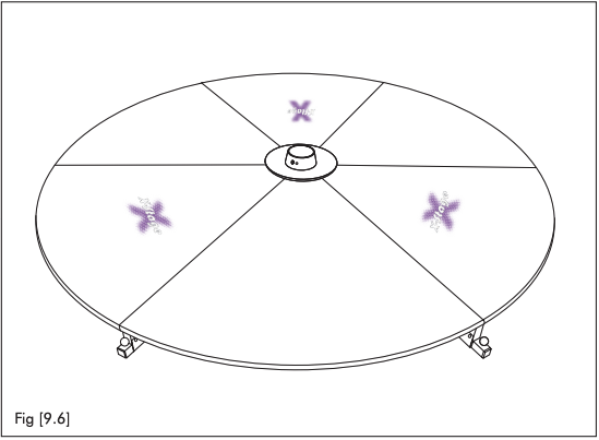
Try to lift the plates
With all six fitted, take hold of a plate edge and pull up on it.
You should see Nothing move. A plate that lifts is a plate whose catches did not engage. The frame is now done, and the pole goes in next.
X-Stage Reminders
- Prior to every use, make sure the screws are tight.
- Do not lift or carry the X-Stage by the plates, this will damage the spring catch pins.
- Do not drag/slide the X-Stage, this will damage the rubber feet.
Those three cover most of the damage a touring stage takes. Two of them are about how you pick it up.
Take the weight on the main frame, knees bent and back straight. The frame is the heaviest single part of the stage.
The plates are held on by spring catch pins, not by the frame. Lifting on them puts the whole stage through those pins and bends them.
The feet have rubber pads that stop the stage walking on a floor. Drag the stage and you tear them off.
The screw check in the first line above is X-Pole's instruction and it covers both sets: the pole retaining screws and the bearing retaining screws. It is the cheapest check on the stage.
X-Stage Modifications
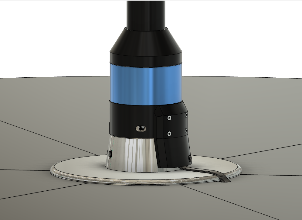
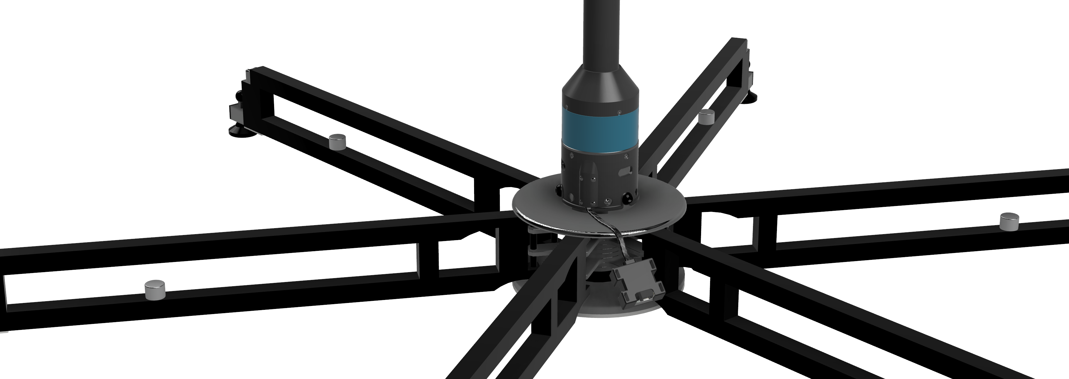
Five things change on a stock X-Stage. Four of them are within a hand's width of the pole, so it is worth learning the names first: every section below points back at this picture.
 1
2
3
4
5
6
1
2
3
4
5
6
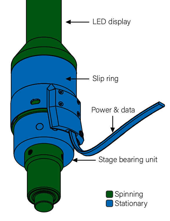
- The pole The lit section, and the part that turns. Everything below it is either bearing or cable.
- Slip ring The band between the pole base and the bearing body. It is why the pole can spin without winding its own lead up.
- Cable block Where the power and data lead leaves the pole. It faces one way, so it decides which plate the lead crosses.
- Bearing retaining screw One of three M10 screws that hold the bearing unit down in the carrier. These are the ones PoleFX replaces with button heads. See Bearing Unit Bolts.
- Carrier and top plate X-Pole's bearing carrier, sitting in the center plate. The bearing size adapter goes inside it. See Bearing Size Adapter.
- The lead Runs across the top plate to the notch in one floor plate, and down. The cover sits over this run. See Floor Plate Notch and Cable Cover.
Bearing Unit Bolts
We provide three M10 button head screws to replace the stock set screws that fasten the bearing unit to the stage frame.
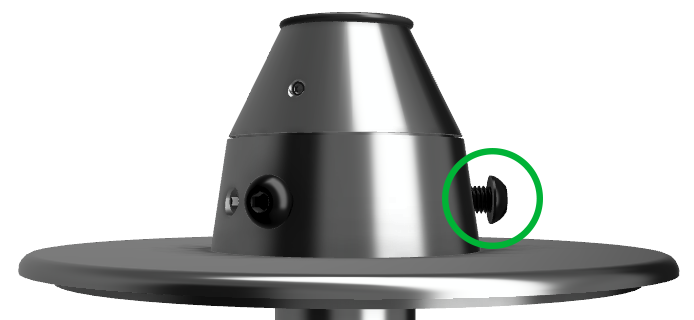
- Head
- Set screw. Sits flush in the cone.
- Thread
- M10.
- How many
- Three, evenly around the carrier.
- What it does
- Holds the bearing unit down in the carrier.
- Head
- Button head. Stands out of the cone.
- Thread
- M10, so it goes in the same three holes.
- How many
- Three. Change all three.
- What it does
- The same, and the proud heads stop the base of the pole and the input cable from spinning.
Pole Retaining Set Screw Replacement
The existing set screws that tighten into the pole are replaced with longer M8 x 1.25 mm thread, 16 mm long set screws.
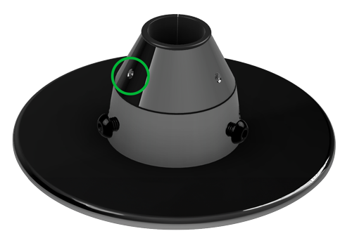
- What it is
- The pole retaining set screws already in the cone.
- Thread
- M8.
- Length
- Whatever came with your stage.
- How many
- Three, around the cone.
- What it holds
- The pole, in the pole holder.
- What it is
- Longer set screws, same style, same holes.
- Thread
- M8 x 1.25 mm.
- Length
- 16 mm.
- How many
- Three. Change all three.
- What it holds
- The PoleFX pole, which sits in the cone with the size adapter around it.
These are not the screws you undo at pack-down. X-Pole is explicit about it: leave the pole retaining screws alone when you dismantle, and take the pole out with the bearing unit still on it. See Pack Down.
Bearing Size Adapter
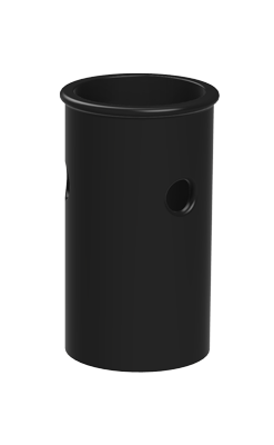
The bearing size adapter is inserted into the bearing unit to adapt the 45mm (1.77") bearing down to the 1.5" steel spigot at the base of the PoleFX pole. An X-Pole pole fills that bearing on its own; ours is narrower where it enters, because the 46 mm polycarbonate stops above the base. That is the whole reason this part exists.
It goes in before the pole does, and it is a loose part, so it is the one to put in first and the easy one to leave in a case.
-
Find the adapter and its top
A short black sleeve, open at both ends, with a rim around one end and holes through its wall. The rimmed end is the top.
You should see A sleeve whose outside matches the bearing bore and whose inside matches the pole's spigot. The spigot drops into the bare bore with several millimeters of slop all round, which is the gap this part fills.
-
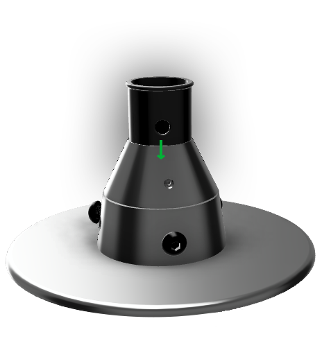
Drop it into the bearing unit
Rim upward, straight down into the bore in the top of the cone. The green arrow shows the direction.
You should see The sleeve go down inside the cone with its rim showing at the mouth of the bore.
-
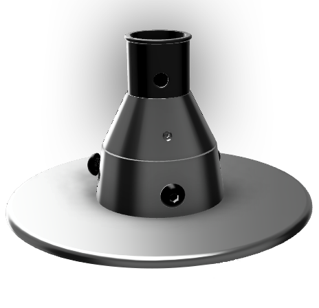
Look down the bore
Same view, no arrow. This is what a seated adapter looks like from above.
You should see A black ring inside the cone, even all the way round, and a smaller hole than you started with.
Floor Plate Notch
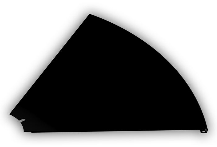
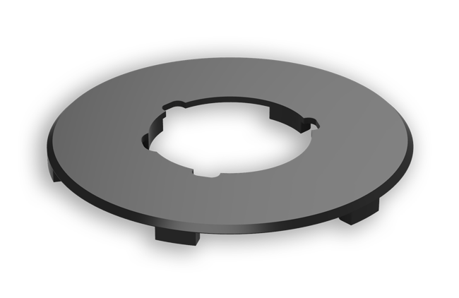
One of the floor plates requires a notch added to the inner edge to allow the pole's cables to tunnel under the stage. Stages provided by PoleFX will already have this modification, and individual modified platforms can be provided.
 1
1
- The notch A half-round cut in the short inner edge, at the narrow end of the plate. This is the only opening between the top of the stage and the space underneath it.
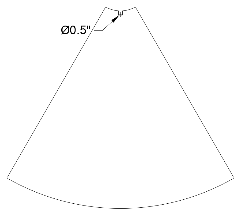
The notched plate has to be the plate the lead crosses. Work out which way the cable block on the pole faces before you start dropping plates in, or you will be lifting one back out. See the modification map.
Cable Cover
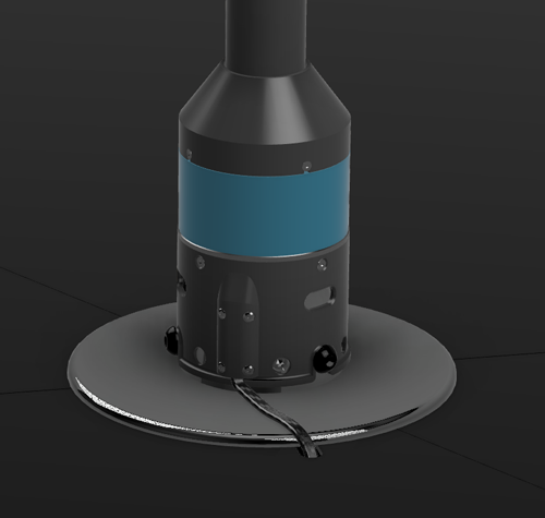
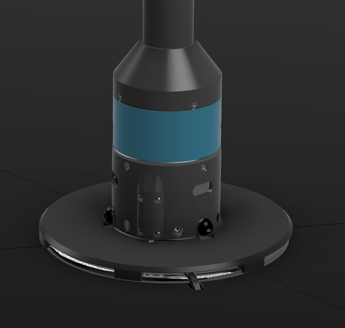
This cover protects the input cable in the exposed section between the notch in the stage plate and the pole.
-
Route the lead first, cover after
Bring the lead out of the cable block, across the center plate, and down through the notch. Take the slack out of it, and keep it in one clean run.
You should see The lead crossing bare metal with nothing over it. This is what you are about to cover, and it is what a heel finds if you stop here.
-
Drop the cover over the base
Lower the ring over the top of the pole base and let it down onto the plate, with the lead underneath it.
You should see No lead between the pole and the notch, and a flat ring you can stand on.
Careful Look for the lead pinched between the cover and the plate rather than running under the arch of it. A cover that will not sit flat is telling you the run is wrong.
Pole Setup
Six steps from a stack of cases to a lit pole. Each one has its own section further down; this is the running order, so you can see what comes before what.
-
Open the stage, plates off
Fan the six sub-frames out and level the feet, but leave the floor plates in their cases for now. See X-Stage Installation.
You should see A six-legged star, standing level, with the bearing carrier facing up in the middle of it.
-
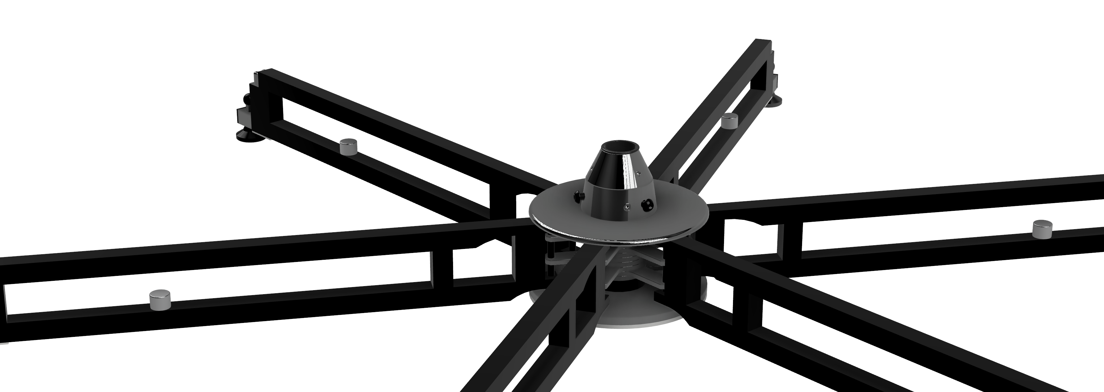
Fit the bearing size adapter
Drop the sleeve into the bearing bore, rim upward. See Bearing Size Adapter.
You should see A black ring inside the cone. Without it the pole's 1.5 in spigot is too small for the 45 mm bore and the pole rattles in the bearing.
-
Stand the pole in, lead first
Keep the pole vertical, feed its lead down through the middle of the frame, and seat the bottom of the pole in the bearing. See Stage Insertion.
You should see The pole standing on its own, with its lead hanging below the frame, and a gap of 1 to 2mm where the bearing unit meets the carrier.
-
Join the sections, two-piece only
Plug the internal cable together, slide the top section on, and tighten the two coupling set screws. See Pole Coupling.
You should see A closed seam with no step in it, and the hex heads sitting in the holes in the upper section.
-
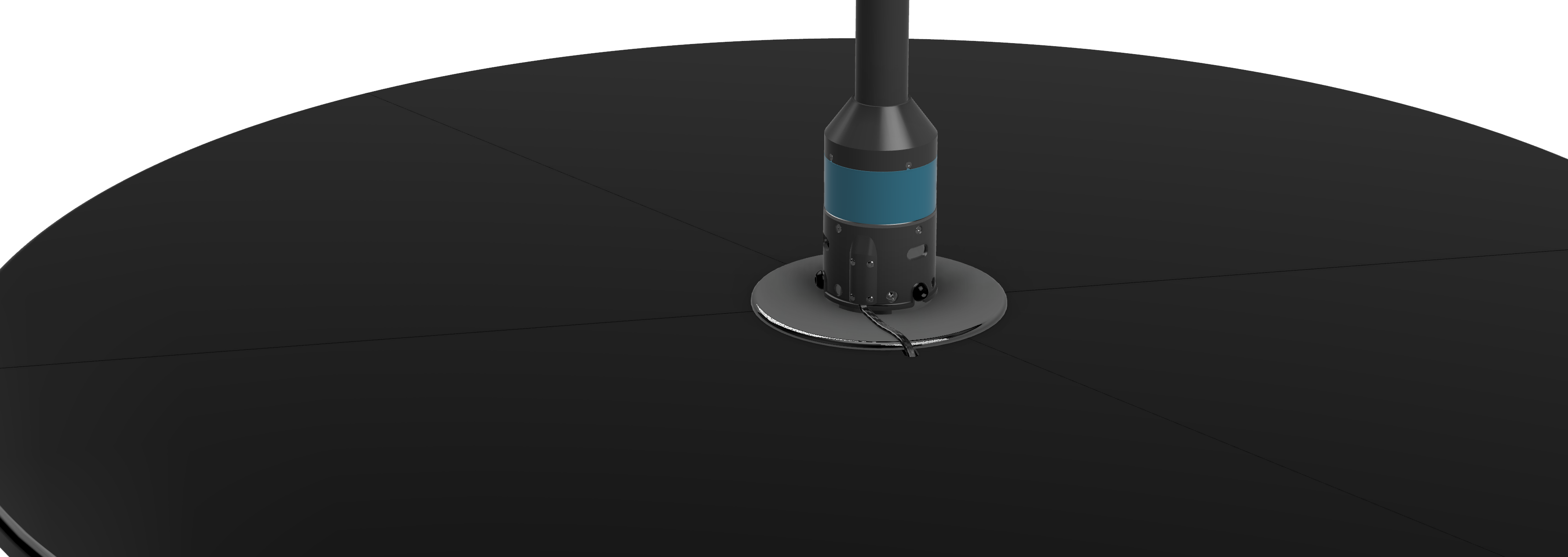
Fit the plates, lead through the notch
Fit the six floor plates, putting the notched one where the lead runs. Bring the lead up through the notch, then connect it underneath to the 5V supply and to the Player. See Input Connections.
You should see A complete floor, one lead crossing the center plate, and a short purple flash at the ends of the pole when the power goes on.
-
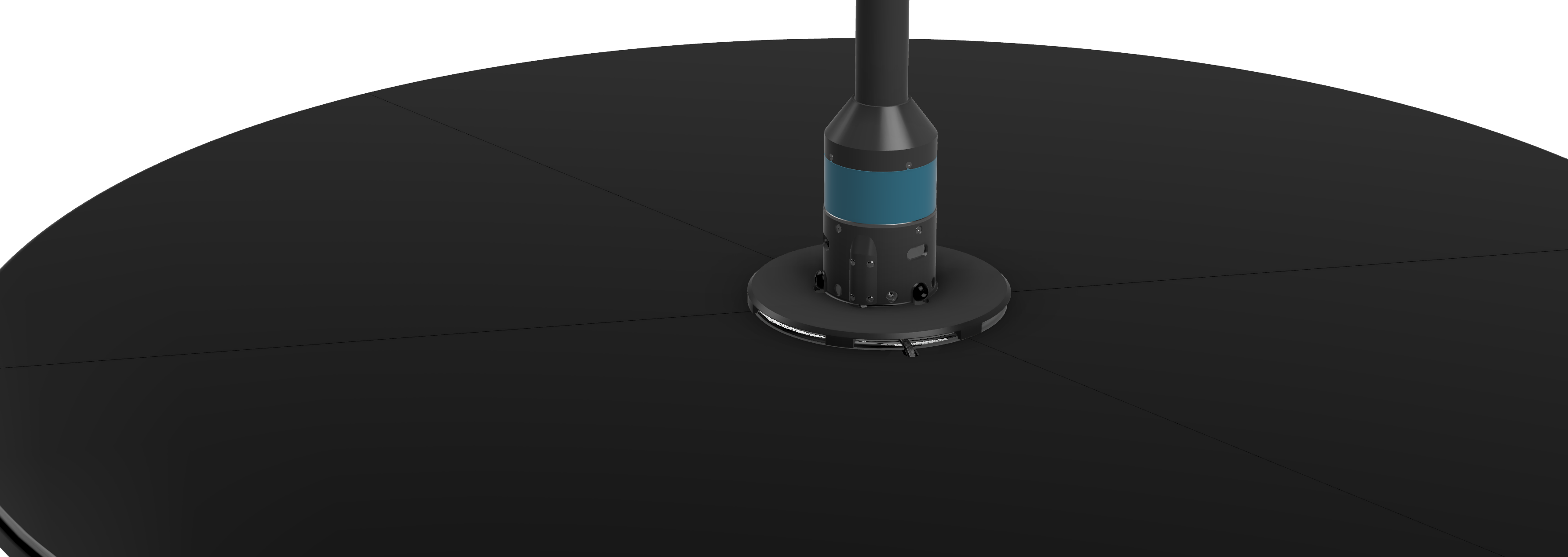
Cover the lead, then test the spin
Drop the cover over the pole base, then set static or spin mode with the 5mm hex key. See Cable Cover and Final Steps.
You should see No lead on top of the stage, and the pole either locked solid or turning freely, depending on which you chose.
X-Pole's manual fits all six floor plates and then stands the pole up. A PoleFX pole has a lead that has to reach the space under the stage, so the order here puts the pole in while the frame is still open. Fit the plates first and you will be taking one back out to pass the lead through.
Stage Insertion
The pole seats in two places at once: the bottom of it drops into the bearing in the base of the frame, and the bearing unit around it drops into the carrier on the center plate. Both have to be right, and the second one has a number on it.
-
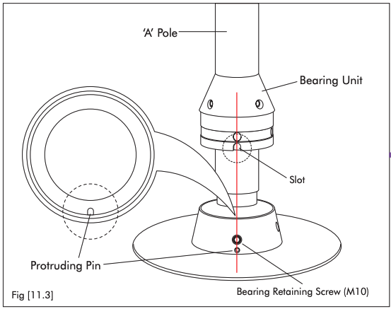
Line the slot up with the pin
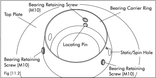
Look into the carrier ring on the center plate: there is a pin sticking up. Look at the bearing unit on the pole: there is a slot in the bottom of it. Keep the pole vertical and slide the bearing unit down so the slot goes over the pin.
You should see The bearing unit drop the last few millimeters and stop turning. If it still turns freely, the slot has missed the pin.
-
Check the gap before you tighten
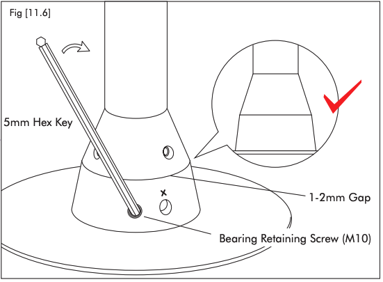
Look at the joint between the bearing unit and the carrier from the side, at floor level.
You should see A gap of 1 to 2mm. More than 3mm means the unit is not seated, and tightening on top of that is what bends things.
-
Tighten the three bearing screws
Use the 5mm hex key. Nip all three up lightly first, going round, then go round again and tighten them firmly.
You should see The bearing unit pulled down square in the carrier, with no rock in it.
Careful Get the key fully into the screw before you turn it. A partly inserted key rounds the socket out, and a rounded screw is one you cannot undo either.
-
Push down, then tighten the set screws
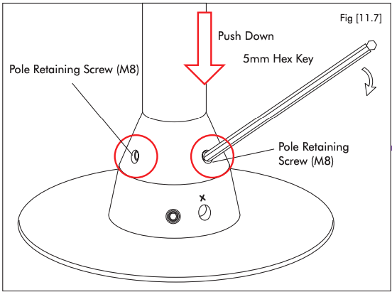
Press firmly down on the pole so the bottom of it is seated in the bearing in the base of the frame, and hold it there while you tighten the pole retaining set screws.
You should see A pole that does not lift and does not rattle sideways in the holder.
The bearing unit is down on the carrier and the slot is on the pin. Tighten from here.
Something is holding the unit up, usually the slot sitting on the pin instead of over it. Lift, turn the pole slightly, and lower it again.
The gap figures, the tightening order, and the hex key size are X-Pole's, from figures 11.3 to 11.7 of the X-Stage Lite manual.
Pole Coupling
Two-piece poles only. A one-piece pole has no coupling, so skip this section. The two sections join about halfway up, and the join is made twice: first the cable inside, then the tube around it. Do them in that order.
The cable inside
Remove the cable from the inside of the top section and plug it into the port in the bottom section.
There is not much slack so this is most easily done while holding the top section vertically in position ready to be inserted onto the bottom section.
The tube around it
With the cable connected, carefully slide the top section into position. Be sure to align hex heads with the holes in the top pole section.
When the sections are aligned, tighten the two set screws in the pole coupling.
To remove the pole sections, loosen the set screws all the way and then tighten them back in one turn. This should allow the sections to be freed again.
Input Connections
A power and data input are both required.
The power supply is 5V, 12A.
The data connection is a Cat5/6 network cable, to connect to a media server or PoleFX player.
Both arrive at the same place: the lead hanging below the middle of the stage. They come from two different boxes, and neither one feeds the other.
The pole's own supply. It does not take power from the Player, and the Player does not take power from it.
An ordinary network cable, to the Player or to a media server. The pole is a network device.
The Player has a single Ethernet socket, not one per pole. More than one pole reaches it through a switch.
 1
2
3
4
1
2
3
4
- Pole base The tapered holder the set screws grip, above the band that lets the pole turn.
- Bearing body The part that drops into the carrier on the center plate. The slot in the bottom of it goes over the locating pin.
- Spigot The reduced end below the bearing. This is what the size adapter is there to fit.
- Lead and connector One flat lead carries both power and data. It hangs below the stage, and everything you plug in, you plug in down there.
Final Steps
When the pole gets power, it flashes at the ends to show it is booting.
If there is no data connection, it defaults to a static pattern.
Once the PoleFX Player boots, the pole will start animating.
Static or spin
Two screws in the bearing body decide whether the pole turns. They are in the holes marked with an X, and they take the same 5mm hex key as everything else on this stage.
- The two X screws
- Tightened, both of them.
- What moves
- Nothing. The pole is locked to the bearing body.
- Use it for
- Normal use, and always before taking the pole out.
- Check it by
- Taking hold of the pole and trying to turn it. It should not move.
- The two X screws
- Loosened, both of them.
- What moves
- The pole turns in the bearing. The lead below does not turn with it.
- Use it for
- Spinning work.
- Check it by
- Spinning the pole by hand and letting it run down. It should turn freely and quietly, with no rub.
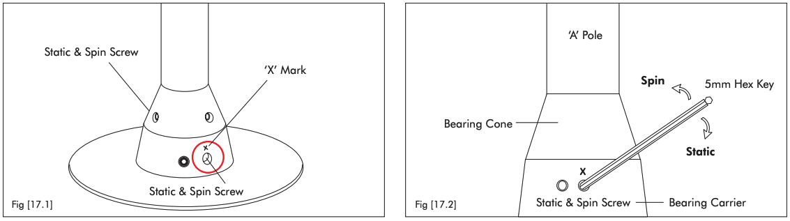
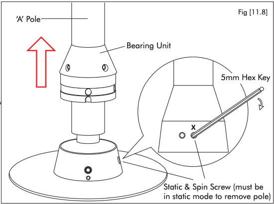
The pole cannot be taken out in spinning mode, and X-Pole says damage will occur if you try. Tighten both X screws before you lift.
Pack Down
Pack-down is setup backwards, with two rules of its own: the pole comes out in static mode, and the bearing unit stays on the pole.
-
Kill the power and unplug underneath
Switch the 5V supply off at the wall, then take the lead off it and out of the Player.
You should see A dark pole, and one free connector under the stage.
-
Lift the cover, free the lead
Take the cover off the pole base and pull the lead back up through the notch.
You should see The lead loose on top of the stage, and nothing left threaded through a plate.
-
Set static, then lift the pole out
Tighten the two X screws, loosen the three bearing retaining screws, and lift the pole straight up with the bearing unit still on it.
You should see The pole come away as one piece, bearing unit included.
Careful Do not touch the pole retaining set screws. They stay tight. The bearing unit is meant to come out on the pole, not stay in the stage.
-
Take the plates off, catches in
Pull the spring catches in as you lift each plate, working back around the stage. Six plates go into two cases, three in each.
You should see Catch pins pulled back in before each plate moves, and no plate being levered against a pin.
Careful Keep the packaging that came in the plate cases. It is what stops the plates marking each other in the van.
-
Retract the feet and fold the frame
Wind the screw adjusters back, push the stabilizer legs in, and fold the five moving sub-frames back toward Sub-frame No.1.
You should see The star close back into a bundle that fits its case.
-
Case it, and wheel it
Strap the frame back onto the sub-chassis in its case the way it came out, and put the hex keys back where you found them.
You should see A stage that rolls on its wheels.
Careful Do not lift by the plates and do not drag the stage. Those are the two ways a touring stage gets broken, and both of them happen at pack-down.
The removal rules, the catch handling, and the folding direction are X-Pole's, from the X-Stage Lite manual.
The pole lights up but never animates
The same five checks apply to a portable pole as to a permanent one, with one extra that is specific to a stage: the under-stage connections are easy to knock loose while you are setting up.
-
If It has been less than about two minutesDo Wait. A still pattern is what the pole shows while nothing is sending it frames, and the Player takes about a minute to boot.
-
If You have just set the stage upDo Check the connections underneath the stage. Both the 5V power and the network cable have to be seated, and both are easy to catch while positioning the pole.
-
If The Player's screen is darkDo The Player has no power. Its supply is separate from the pole's.
-
If The Player is up and the cable is seatedDo Check that this pole's output is switched on, in Settings > Outputs. An inactive output means the Player sends it nothing.
-
If It animates but looks wrongDo That is a different fault. See the pole symptom list.