Permanent Pole

Specs
| Feature | Description |
|---|---|
| Configuration | Single Piece |
| Length | Up to 12ft |
| Diameter | 46mm |
| Power | 5VDC, 60W |
| Data connection | Ethernet |
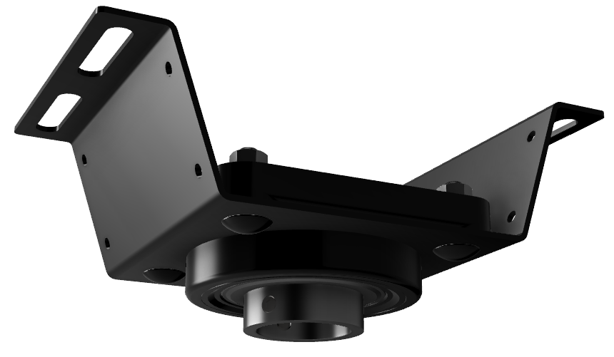
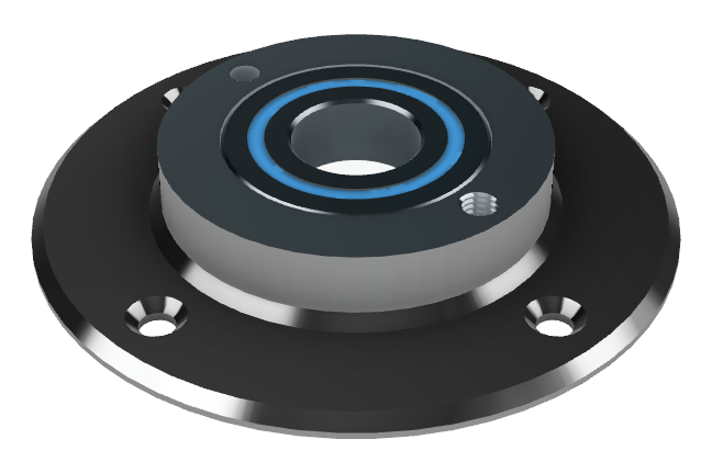
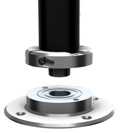
| Mounting | Top and bottom bearings |
Sizing


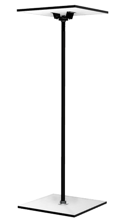
Each permanent pole is custom built to fit the size of the space it is being installed in.
The pole has an unlit section at the top that interfaces with the upper bearing, and a variable length LED display (up to 10' tall). Beyond a 129" ceiling height, the top unlit tube is lengthened to reach the intended total length.
There is typically about one inch of clearance between the top of the pole and the surface it is being attached to. This gap is necessary to be able to remove the pole without taking down the mounts.
Pole Setup
Step 0. Gather Supplies
You will need: - Appropriate mounting hardware - A partner - Drill or other tools for installing fasteners - Ladder - Level
Download hole templates
Step 1. Decide Which Mount to Install First
- If you must align with a ceiling beam, install the top mount first.
- If the position of the bottom is more critical, install the bottom mount first.
Step 2. Install the First Mount
- Position the mount (top or bottom) in the desired location.
- Drill any required pilot holes for mounting hardware.
- Secure the first mount firmly.
Step 3. Insert the Pole to Mark the Second Mount
- Place the pole into the installed mount.
- Hold or support the free end of the pole vertically, ensuring smooth spin.
- Mark the holes where the second mount will be attached.
Step 4. Install the Second Mount
- Drill any required pilot holes for mounting hardware.
- Secure the second mount firmly.
- Check that the pole remains straight and can rotate freely.
- Tighten set screws in top bearing collar to prevent pole from being lifted up.
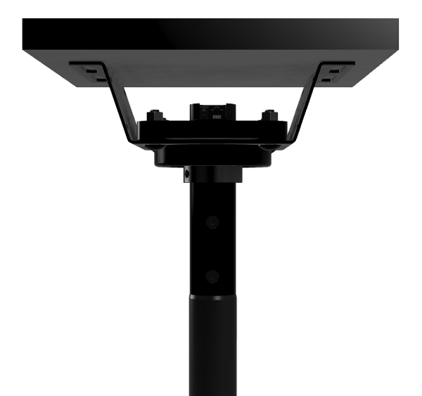
Step 5. Plug in Power and Data at the Top
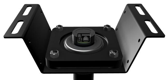
- With the pole fully seated in both mounts, connect the power and data cables at the top.
- Tie off the cables to minimize movement as the pole spins under them.
- Mount the pole’s power supply near the top mount, or extend the cabling as needed.
Step 6. Connect to the PoleFX Player
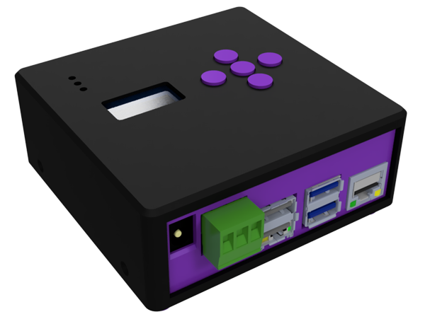
- Use a network cable to connect the player to the pole.
- Plug power supply into player.
- Wait about a minute for the system to boot.
Note: When the pole gets power, it flashes a short purple section at the top. The pole will display a static pattern if there is no network connection. The full display is activated once the Player boots.